


Usage of Surge Arresters in HV system (Panel Discussion on Electrical Safety Regulations)
- Vidyut Surakshit Bharath Abhiyan
- Mar 27, 2022
- 5 min read
Panel Discussion on Electrical Safety Regulations - Question 8
74. Protection against lightning.-
(1) The owner of every overhead line, sub-station or generating station which is exposed to lightning shall adopt efficient means for diverting to earth any electrical surges due to lightning which may result into injuries.
(2) The earthing lead for any lightning arrestor shall not pass through any iron or steel pipe, but shall be taken as directly as possible from the lightning arrestor "without touching any metal part to a separate-vertical ground electrode or junction of the earth mat already provided for the sub-station of voltage exceeding 650 V subject to the avoidance of bends wherever practicable.
Answered by Shri Jameskutty Thomas
Any Surge Arrester, be it HV or LV, if the connecting lead length is higher, the arrester is ineffective. As a result connecting the earth connections of Surge Arresters to a separate earth electrode is wrong. Hence the para 2 to be modified accordingly since it is creating confusion to users, leading to wrong connection and usage.
The following references from IS/IEC & IEEE are explained
IS 15086 : Part 5 : 2020/IEC 60099-5 : 2018 Surge Arresters Part 5 Selection and Application Recommendations.
Clause 5.2.5.5.4 Connection leads
The location of the distribution arrester relative to the protected equipment can be very important when considering the fast rising lightning surge. When protecting from fast rising surges the lead length in series with the arrester and in parallel with the protected equipment can generate a significant voltage due to its inherent inductance. This lead voltage is in addition to the fast front characteristics of the arrester. The connections shall be installed as short and straight as possible. This is because inductive voltages appear at each conductor due to the self-inductance during the flowing of the impulse current. These inducted voltages are considerable during high rate of changes di/dt, such as when lightning currents occur. The MO material itself reacts almost instantaneously even with very steep voltage and current impulses In view of the dimensions of the arrester itself and the connections, there are always inductive voltages and it is necessary to take them into account. If the residual voltages found in the datasheets do not contain an inductive voltage drop corresponding to 1 μH/m of arrester length, then the arrester height must be considered.

fig: Examples of good and poor connection principles for distribution arresters
The additional inductive voltage is consequently calculated as:

A voltage of Ui = 10 kV per meter of connection lead results from a steep current impulse with a rise time of 1μs and 10 kA peak value. This means that the connections and the entire loop shall be executed to the greatest degree possible without inductance. Both the arrester and the transformer shall of course be connected at the same earthing point.
IEEE 142.
2.2.7 Grounding connections associated with steep wave front voltage protection equipment The application of surge arresters to transformers (see Figure 2-7) and surge protective capacitors and arrestors to rotating machines (see Figure 2-8) illustrates this application of a grounding conductor. The function of the grounding conductor is to provide a conducting path over which the surge current can be diverted around the apparatus being protected, without developing a dangerous voltage magnitude.
In the presence of a changing current (di/dt) there will be an inductive voltage drop developed along the grounding conductor itself, which is additive to the protective device voltage. The amount of this added voltage will be proportional to the conductor length and the spacing from the protected apparatus and of course to the magnitude of di/dt.
Actual values of di/dt range over wide limits, but a value of 10 kA/μs is representative. With such a rate of rise of current, even 1 μH of inductance can be significant [see Equation].

It would take only a 0.88 m (3 ft) length of 95 mm2 (4/0 AWG) conductor spaced 1.52 m (5 ft) away from the transformer in Figure 2-7 to add 10 000 V to the arrester voltage. Thus, grounding conductor length and spacing become of paramount importance. One can readily visualize that the additive inductive voltage is generated by the total flux linkages that can be developed through the window between the grounding conductor and the protected apparatus.
To take full advantage of the protective properties of the surge arrester in Figure 2-7, the arrester should be mounted so as to be in direct shunt relationship to the terminal bushings. At lower voltages, an arrester supporting bracket can usually be extended from the base of the bushing. At higher voltages, a shelf extending from the tank body at the proper place to minimize the inductive voltage is often used to support the arresters.
Locating the arrestor at any substantial distance, such as at the pole-top crossarm, with an independent grounding conductor can seriously increase the surge voltage stress on a transformer or switchgear by the voltage drop in the arrestor down lead to ground.
Arresters should be as close as possible to the equipment to be protected and to ground. The same fundamental reasoning applies to the installation geometry of rotating machine surge-protective equipment (see Figure 2-8). A box, shelf, or bracket directly adjacent to the emerging leads from the machine can accomplish the desired objective.

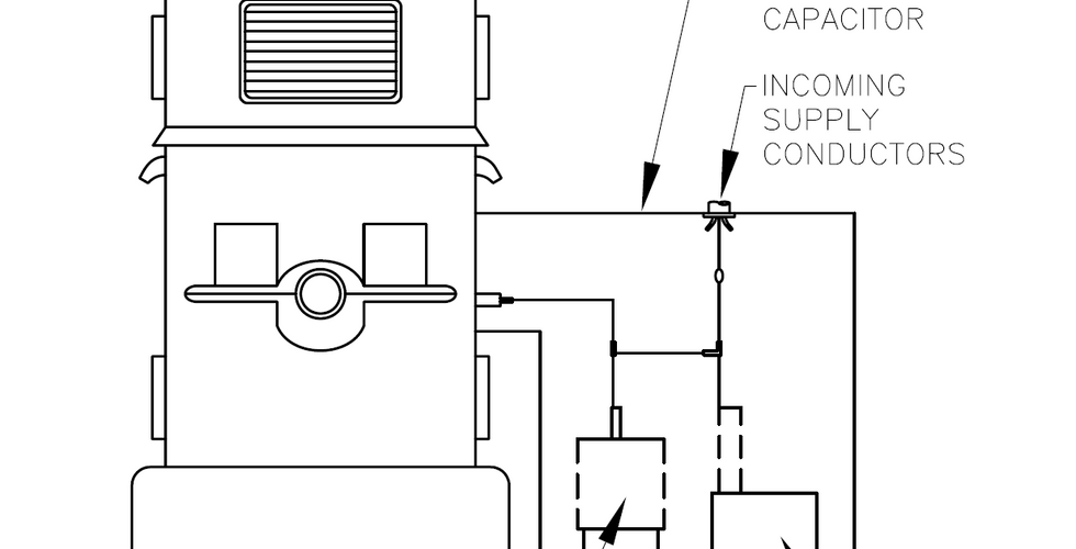


Figure 2-7—Surge arrestor location on transformer & Figure 2-8—Surge protection equipment on motor (only one phase shown for clarity)
The mounting frame should connect directly with the machine frame to minimize the circuit inductance. It is the capacitor element of the protection system that deserves prime attention. If this item is properly connected with short, direct connecting leads, the rate of rise of voltage at the motor terminal will be quite gentle, requiring perhaps 10 μs to build up to arrester sparkover value. Thus, the leads to the arrester can be longer because of the modest rate of rise of voltage. In fact, there can be a benefit from inductance in the arrester circuit, which cushions the abrupt drop in machine terminal voltage when the arrester sparks over.
IS732: 2019 Clause 5.3.5.2.9 Connecting conductors
Connecting conductors are the conductors from the line conductor to the surge protective device and from the surge protective device to the main earthing terminal or to the protective conductor.
Because increasing the length of the connecting conductors of SPDs reduces the effectiveness of overvoltage protection, optimum overvoltage protection is achieved when all connecting conductors of SPDs are as short as possible (preferably not exceeding 0.5 m for the total lead length) and without any loops (see Fig. 59). If distance a + b (see Fig. 59) cannot be reduced below 0.5 m, the scheme in Fig. 60 may be adopted.


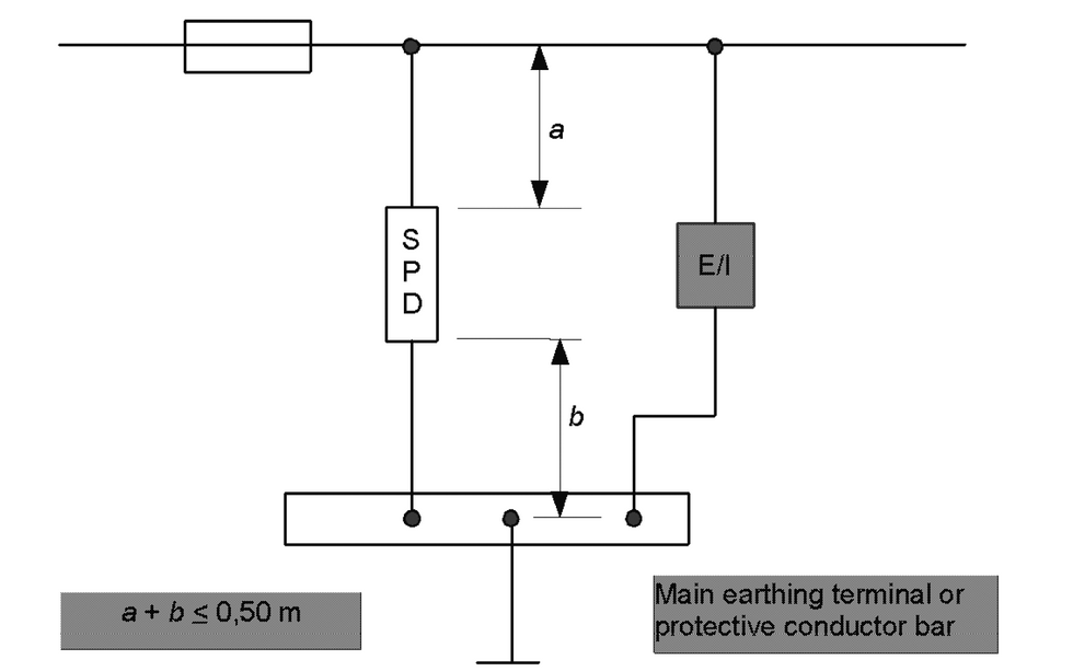
FIG. 59 EXAMPLE OF INSTALLATION OF SPDS AT OR NEAR THE ORIGIN OF THE INSTALLATION & FIG. 60 EXAMPLE OF INSTALLATION OF SPDS AT OR NEAR THE ORIGIN OF THE INSTALLATION.
Any Surge Arrester, be it HV or LV, if the connecting lead length is higher, the arrester is ineffective. hence the connection as per the IS/IEC shall be followed.
Videos of the main program
Details of the main program


Comments